I have some problem with my newton's power supply. The purple line have 5 volts but it can't start.
Then i decided to replace caps in secondary side but nothing change.
If anyone can help me please tell me howto fix it.
I attached some pictures of this power supply.
My English is also at the level of translate.google.com
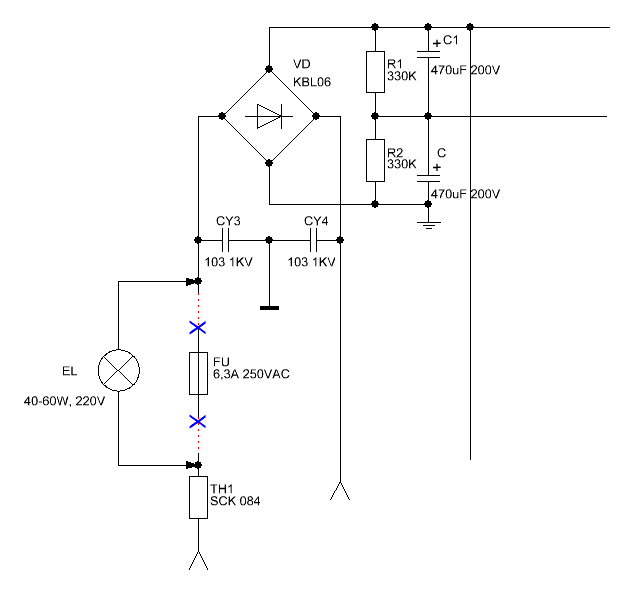
Replace the fuse on the incandescent lamp (~ 60W) for the protection of power transistors. Find optocoupler, which controls the main power
If the output is not short circuit, jumper pin 2 coupler to the ground and if the lamp is not lit, measure the output voltage...
Hi SpyFlash!
Incandescent lamp (lighting) does not belong to the scheme of your power supply. It is necessary to limit current consumption and to prevent failure of the circuit components.
For example:
Place the image block to a more accessible (we) file repositories on the network. If possible reduce the amount of images
Yes, on-board 3 coupler. One - the stabilization +5 SB, the second - the stabilization of the main power supply and a third that we need.
With the closure of the green wire to black, it opens and enters the voltage on the PWM.
But if a few seconds leaving no voltage in output, with the coupler off the voltage
Replace the electrolytic capacitors on the submodule.
Snap a photo of a large connector: why purple ? May be violet ?
У кошки 4 ноги... Вход, выход, земля и питание.
@UAM
i replaced electrolytic capacitors. after short green and black not work.
why purple ? May be violet ?
Violet. a little confusing in english.
My English is also at the level of translate.google.com
Replace the fuse on the incandescent lamp (~ 60W) for the protection of power transistors. Find optocoupler, which controls the main power
If the output is not short circuit, jumper pin 2 coupler to the ground and if the lamp is not lit, measure the output voltage...
У кошки 4 ноги... Вход, выход, земля и питание.
Hi UEM,
Replace the fuse on the incandescent lamp > Could u please make in snapshot? I don't know where is it. No lamp on this board.
Find optocoupler, which controls the main power > See in picture.

Back curcuit line of optocoupler

Hi SpyFlash!

Incandescent lamp (lighting) does not belong to the scheme of your power supply. It is necessary to limit current consumption and to prevent failure of the circuit components.
For example:
Place the image block to a more accessible (we) file repositories on the network. If possible reduce the amount of images
What missing an element on the board ?
Yes, on-board 3 coupler. One - the stabilization +5 SB, the second - the stabilization of the main power supply and a third that we need.
With the closure of the green wire to black, it opens and enters the voltage on the PWM.
But if a few seconds leaving no voltage in output, with the coupler off the voltage
У кошки 4 ноги... Вход, выход, земля и питание.
Hi UAM,
How to find a schematic of this power supply? I don't under stand power circuit.
a third that we need = Is it near violet line (in picture above)? Could u please explain with picture diagram instead.
Thanks.
У кошки 4 ноги... Вход, выход, земля и питание.
I will try tonight. If found not i will ask you again tonight or tomorrow.
BTW thank for ur help.
Hi UAM,
Sorry for late reply. today i have no time for testing coupler. but i found a datasheet of it (ET1104).
What missing an element on the board ? = miss answer... it is a transistor but i put it already.
here is a link of ET1104
pdf1.alldatasheet.com/datasheet-pdf/view/252415/VISHAY/TCET1104G.html
output Vce = 70
Vec = 7
i will test tomorrow.
Отправить комментарий